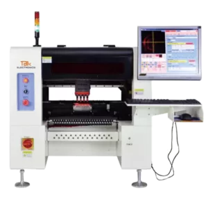
Desktop Pick And Place Machine – DT4H
It is the fastest pick-and-place machine among the products in the same class of desktop around the world. With the optimum 13,000 CPH, it also has a large component range. More importantly, it reaches a high X, and Y axis resolution accuracy of 0.1mm, and can meet the high standard production requirement.
The core parts such as the driven motor come from credible brands that are well-known in the world, which improve the machine’s total working capability and enhance the stability, owning efficient placement of electronic components from 0201 to 40 mm.
This type of desktop pick and place machine is also applicable for the small-sized SMT production lines, and it has a competitive price as compared to other placement machines with the same performance.
1. Overall Hardware Parts
- It adopts high-standard core parts which are mostly imported from reliable brands all over the world. Each component is highly matched to complete the high-precision and high-speed placement process.
2. X, Y axis Driven by Double Ball Screw & Linear Guide Rail
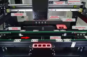
- DT-4H desktop pick and place machine adopt the imported Taiwan TBI high-precision ball screw to drive, which can effectively ensure the high accuracy placement of 0201 chip and IC, BGA components.
- With high-speed linear guide rail, the transportation process is silent and also can transport precisely.

3. Simultaneously Recognition of Four Groups of Camera
- Equipped with 4 groups of component recognition camera, the desktop pick and place machine could realize the fast speed of the visual recognition process which is really efficient.

4. High Pixel Visual Calibration Camera
- Equipped with 5 million pix camera from Sony, which ensures the high accuracy of component placement and improve the placement stability.

5. Applicable to 0201 Chip Component
- It is applicable to mounting the 0201 chip with high accuracy as well as keeping a high speed of 7000 CPH.

6. Equipped with Servo Motor from Panasonic
- The X, and Y axis adopts a Panasonic servo system with strong performance, which has high mechanical adaptability and ensures long-term stability and precision of mechanical use.

7. Four Spindles Design
- DT4H can optimize capacitor, resistor, and mounting heads to realize simultaneously picking the components, automatically reducing the movement speed before placing the components, which improves the efficiency of common components mounting, ensure chip mounting speed.

8. Imported Electromagnetic Valve
- DT-4H desktop pick and place machine adopts a vacuum generator and the vacuum power is strong and stable.
9. Long Service Life of Tank Chain
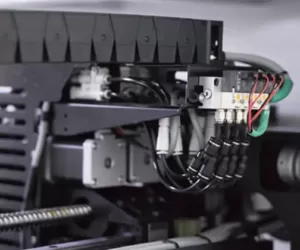
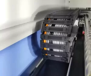
- High pressure mute durable tank chain is adopted, which has the same quality as overseas brands, plus reasonable wiring process, the service number up to millions of times.
10. Intelligent Operating System
- Adopting with the standard industrial computer, it supports W7/10 operating system, which is humanized and convenient.
- Also, it supports visual programming and realizes fast switching optimization after importing PCB engineering files by one-click.
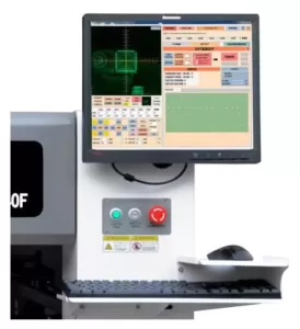
11. Stylish Design Of The Outlook
- The entire DT4H desktop pick and place machine uses the latest machine outlet design, it is intelligent to operate and improve the running efficiency.

Something you need to know about
DeskTop Pick And Place Machine
1. The Desktop Pick and places Machine
1.1 Who needs the desktop pick and place machine?

ElectronicsTalk Desktop Pick and Place Machine
1) If you require higher placement accuracy and keep with the high speed than hand assembly or manual/semi-automatic machines;
- You have a larger production capacity, such as tons of components on your board;
- You don’t need to possess to put all the components yourself, one at a time;
- You got to build boards faster than you’ll with a manual or semi-automatic system;
- The income from the products you will be making (and/or your ability to require contract jobs on top of your own products) justifies an investment in a benchtop machine.
1.2 Manual or semi–auto desktop pick and place machine

Manual Desktop pick and place machine
These are the small amount for the expensive models, typically selling between $1,000 and $12,000. The kind of desktop pick and place machines range from something as simple as board handling, arms resting, placement of components, and a vacuum generator structure to optical vision systems, but also it is a desktop solution for surface mount technology.
Besides, it also has the control function of component lowering, a system of placement head guiding, motorized parts carousels, tape and strip feeder ability, and more.
All of the manual and semi-automatic placers have one thing in common: you’ll be involved in placing every single component on every single board. Different from the automatic pick and place machine, you could not simply feed a board and just let it go.
1.3 When do you need the manual desktop pick and place instead of the full automatic?
You are probably within the marketplace for a manual or semi-automatic system if:
- You don’t expect to be assembling tons of boards;
- You’re building too many boards for hand assembly to be feasible;
- High precision (repeatability) and accuracy aren’t critical to your products;
- You require more accuracy than you’ll get with hand assembly;
- The income from the products you will be making won’t be high enough to justify an automatic machine.
2. Usual Centering Methods For Desktop Pick And Place Machine
2.1 No centering mechanism
Other than counting on the component’s pick-up point for placement.
In other words, the part isn’t physically centered after being picked up by the tool head, and if it’s picked off-center on the tool, it’ll be off-center when placed on the board.
Obviously, this is often not a really accurate placement method because there’s no definable tolerance.
You’ll expect to seek out this method employed by hobbyists or instructors, but never in any sort of precision production environment.
There aren’t many options available either, and long-term reliability is questionable.
- Pros: Low cost.
- Cons: Low accuracy and repeatability, short-term reliability, no options or spare parts.
c: Dimension: Non-definable
2.2 Mechanical centering jaws or fingers

Mechanical Centering
In this method, the machine picks up components and moves them onto their center positions within the X, Y axis at the placement head.
Typically, this method is straightforward to line up and repeatable within 0.001” accuracy. This centering method is usually found in low- to mid-range machines.
- Pros: Easy to find out and set up; repeatable; one of the fastest method is currently available; a real “on-the-fly” system; low cost.
- Cons: Physically touches the component which can not be appropriate surely sorts of parts, especially those with delicate leads.
- Size range:0201 up to 35 mm square.
2.3 Laser Centering
Under this system, the machine picks up the component online with a ray, which can detect the center position of components on the head.
Besides, which also recalculates the zero of the part consistent with its position within the X, Y axes, and rotational position relative to the top for accurate placement on the board.
- Pros: Touchless; on-the-fly (similar to the mechanical method).
- Cons: it’s less reliable. There are limitations on the kinds of parts it can handle, like very thin components (If .050 thin, sometimes, the operator needs to reset them due to part variations, even from an equivalent vendor);
Also, it requires a longer setup time, since the machine must define the Z-axis (part thickness); more so it is more costly than Mechanical Centering but about equivalent to Vision.
- Size range: it is not able to center parts smaller than 0402 packages or larger than 35 mm square.
2.4 Vision Centering
Generally, there are two types, Look-Down and Look-Up.
- Look-down vision will view the highest of the component before picking it up for its pick-up location.
It then calculates its centering location and compares it to its image file from the stored database, then picks up the components and transfers them to their position onto the printed circuit board.
- Pros: True touchless centering; enable to handle odd-shaped and delicate components; Its placement accuracy can reach to 4 microns.
- Cons: Typically, longer setup times thanks to the necessity to show the vision system the way to identify part images which are stored within the machine’s database; a slower method of centering thanks to the time slice required for processing;
- Applicable component range: 0402 – 15 mm
- The Look-Up Vision method is the most accurate centering method available.
The component is first picked up from the pickup area, moved to a camera station that appears at the rock bottom of the component, and calculates its center position.
- Pros: True touchless centering, handles delicate components; accurate right down to 1-micron positioning accuracy;
- Cons: Typically, an extended setup time thanks to the necessity to show the vision system the way to identify the image, stored within the machine’s database; a slower method of centering thanks to processing time; Vision is more costly than the mechanical method.
- Size range: 01005 – 50 mm
The Pick-Up and Centering Method you select will have an excellent deal of influence on the standard and speed of your production needs, alongside the way to relate this accuracy back to the machine. But, that’s just the start.
As with any complex machine, there will be tradeoffs between capabilities and cost, various of which specifically point to production accuracy and yield. Then, we will address the next factors below:
- Mechanical positioning methods
- Machine construction
- Solder paste fluid dispensing
- Component feeders
3. How to DIY desktop pick and place machine
The trend of building DIY pick and place machines is gradually popular recently. In this section, we will illustrate the process from the basic assembly to the final stage of making one desktop pick and place machine, there are 9 steps normally for manufacturing, so let us look throughout the below.
3.1 the ground Plate Assembly
It is important that the DIY pick and place machine owns a solid and stable ground plate, which is the foundation support.
Firstly, the method needed to notice is placing the floor plate assembly under the Y-Axis assembly. It encloses the controller, two valves for pressure and vacuum as well as a USB-Hub.
Why we should have a USB hub?
The reason why is that we need to attach the controller and two USB-Cameras to it. Moreover, there’s a connection box for the vacuum at the side of the ground plate, pressure, and power supply from the external control box and therefore the main USB connector.
Since the complete machine is based on the ground plate, this step is essential and once it is completed, other parts of the machine will be ready to install. This seems like repairing a car and every part inside is easily accessible.
Besides, a big part of the rock bottom plate is empty. The free space is employed for the cables and tubes that run to the axes. The cables can move freely in this area.
3.2 Y-Axis and Machine Bed
Secondly, it turns to the step of building the Y-axis and machine bed, we also called the machine foundation.
The Y-axis is driven by the motor that controls the direction at a 90 degrees angle of the X-axis. It is one of the determining factors of movement precision during the placement process.
And a machine bed is the basic structure when the machine running.
The way is that we can use the aluminum T-slot profiles from 20mm to 40mm on the front and backside of the unit for the machine bed.
The edges of the machine bed adopt solid aluminum profiles, and the edges carry 15mm linear rails that hold the Y-axis.
Then, in order to drive the Y-axis, we need to attach a 125W BLDC motor with a 500 imp/rev (2000 imp/rev in X4 mode) encoder to at least one of the side profiles.
Using the HDT5 drive timing belts on each side which will move the axis. Besides, the belt disks on each side are connected by using 8mm shafts that are supported by 3 bearings.
Next point, the reference switch (blue, check the second picture in the following) is triggered by the Y-axis in its home position. It will be easy for a PCB cabling that is near the motor.
Later, the printed circuit board will be placed onto an adjustable PCB holder formed by 20mm*20mm aluminum T-slot profiles.
And other profiles of an equivalent type on the machine bed are used for mounting the fixed vision camera, part trays, and single parts.

Y-Axis and Machine Bed
3.3 X-Axis
The third step of building your own DIY pick-and-place machine is the X-axis.
The X-axis is controlled by the motor in the horizontal direction, which is also a key to effect the movement accuracy of the placement head.
When comes to the DIY pick and place machine, it works the same function. The X-axis is reposed on a solid aluminum profile, which is used to maneuver the axis.
A 15mm linear bearing and HDT5 timing belt are used.
In addition, two bearings support the belt disk on the other side of the motor, and the motor may be a 62W BLDC motor with a 500 imp/rev encoder (2000 imp/rev in X4 mode).
The movement area is 620mm. The axis that is mounted on top is a cable channel for guiding the cables that run to the place head. It is additionally wont to hold the X-axis motor.
The printed circuit board also connects with the reference switch of the X-axis.
Then, the X-axis is able to move onto the machine bed to succeed in the feeder blocks that are placed on both the front and rear sides of the machine.

X-Axis
3.4 Four Units of Placement Spindles (Z axis)
The fourth point is the placement spindles, which are equipped with two Z-axes.
The Z-axis is located in the vertical direction basis on the X and Y-axis to control the up-to-down movement.
The working principle is that one among them moves the nozzle up and down while the opposite one contains the paste.
Both axes advance 9mm linear rails. they’re driven by 42mm stepper motors which finish up a bit of two 5mm timing belts (for the entire movement area of 32mm only half a turn of the belt disk is used).
Another point that needs to be noticed, the linear axis can be only moved upward. It’s because the movement in the down direction is completed by gravity. And both Z-axes are equipped with reference switches that are triggered within the upper position.
The axis used for pick and place operation is carried by a 28-millimeter hollow shaft stepper motor that rotates the nozzle.
On its lower drive, adopting a hoop magnet that is mounted using stud screws. Besides, the magnet holds the nozzles by using magnetism.
On its upper drive, it is connected to a bit of flexible pneumatic tubing, which is using an aluminum block with a gasket that is pressed onto the driveshaft with two springs.
The mounting plate of the rotary motor is roofed by a black plate to extend the contrast when components are aligned by the fixed camera.
The Z-axis is holding the paste that carries a holder for paste syringes, weighted 35g. The syringe ram is moved via a linear stepper motor of 28mm with a lead screw.
On the downstream end of the lead screw, an aluminum ring is placed. It protects the lead screw from turning around at the time when the paste is squeezed out of the syringe.
And the entire linear stepper motor assembly is often removed to exchange the syringe.
Moreover, the positioning head equips a camera with red LED bars. The function of this camera is for fiducial alignment and visual inspection after placement.
A printed circuit board that is connected with all electrical components on the positioning head is assembled on top.
Also, the printed circuit board includes a pressure sensor. The pressure sensor recognizes a neighborhood that is held onto the nozzle by evaluating the vacuum level. It’s looped into the pneumatic tubing.
3.5 Nozzles
The fifth step is the nozzle part, which is turned from brass.
In general, a nozzle is used to suction the components by its vacuum generator located on the placement head. And then placing them on the PCB board that is assembled.
While, during the mounting process, mounting onto the nozzles may be a ring magnet that holds them on the location head alongside the second magnet which is on the lower end of the hollow shaft stepper motor.
Thus, they need to be shielded from slippage. You will use a bit of silicone pad that’s shown in the photographs below.
It enables to replacement of the silicone pad on the nozzles in the method that the silicone pad is underneath the rotary axis.
Also, you will paint the lower part of the nozzles that are used for component alignment.
Lastly, the nozzle holder can have 3 nozzles at the most, then the machine can exchange the nozzles automatically.
3.6 Cameras
Then, the next step is to focus on the camera part. The cameras are equipped with a DIY pick and place machine including two units and they are also called USB cameras.
The first camera is mounted onto the positioning head alongside two LED strips employing a milled aluminum holder. It is wont to detect fiducials and to visually inspect the PCB board after placing the components.
The second camera is fixed on the bed of the machine. It is built from pieces of PCB and used for component alignment. The parts are illuminated by using LEDs in red and green which will be adjusted in intensity.
The camera is roofed by a bit of glass that is cut from a microscope probe carrier. This bit of glass is often important because this camera is easy to be broken.
Vision is computed using OpenCV.
3.7 Controller
A controller is also important for the process. The controller of the DIY pick and place machine contains the following circuit blocks, if you want to build the same one, the following points are important to look at:
1) X and Y-axis BLDC Controller.
2) A 12V DC-DC converter for the FET drivers for the B LDCs;
3) Z1, Z2, R1, R2 stepper motor drivers;
4) A couple of logic level driver FET for LED, vibratory feeder, two solenoid valves for vacuum and pressure, then vacuum pump and other extensions;
5) Reporting the state of the vacuum sensor;
6) USB-Interface (serial over USB).
The controller board is under the machine bed. An external control box is additionally necessary. It contains the facility supply, the air pump, the reservoir, and a pressure reduction valve for the compressed gas.
3.8 Automatic Feeder
Next, the Feeder system of the DIY pick and place machine starts to consider. An automatic feeder bank has tons of benefits compared to a pin-driven feeder. And the common goal was to make the plan simple
The best thanks to advance the tape is to finish up the tape only. The matter is the way to detect the position of the tape.
An optical solution employing a photodiode and infrared LED to detect the holes within the component tape.
It is the easiest method but doesn’t work for clear tapes. A mechanical detector solution will work for all types of tapes.
3.9 The Software
The final step is the design of the software. One of the purposes of using the software for a DIY pick and place machine is to stay the most program free from commercial. It is split into a few separate programs. The programs are called the most program:
1)The main pick and place software with its driver DLL that communicates with the machine.
2)An external CAD program that is wont to generate part footprints, import Gerber files, and define the PCB. Next, it will simulate the process of component placement onto the feeders.
3)A script-controlled program wont to import centered files.
4)A program to get part packaging (part tapes, trays, or part tubes).
4. Some Criteria For Select Your Own Desktop Placement Machine

Right-Selection-Logo
If you are a low-volume electronics manufacturer or a hobbyist stepping up from hand assembly, you would possibly be overlooking how efficient you will get in production by continuing to try to hand assembly.
Tons of individuals doing just through-hole soldering could be nervous about the surface mount. They could even be tweezing their way through work, which isn’t the foremost efficient thanks of doing things. There are many things that you simply can do to urge more efficiency.
There is a different flavors of benchtop or desktop computer circuit board (PCB) assembly solutions available.
Desktop SMT equipment should be compact, yet flexible enough to hide a good spectrum of today’s manufacturing needs and within the future, too. These should even be easy to use and economical.
Let us take a glance at a number of the items that you simply got to consider while buying a PNP machine.
4.1 Select the proper feeders
The components now come on paper or plastic tape. So if you’re assembling manually, you’d just got to hold on to the tape somehow.
In PNP, you would possibly get machines where there’s no facility to advance the tape then you’ll need to take care so as to not spill the components everywhere on the workbench.
It will be a pain to map out the tiny components, especially if these are polarized. The last item you would like is to transform the entire thing.
The desktop pick and place machine provided by ElectronicsTalk can be equipped with a maximum of 50 slots of feeder capacity.
And both the rear and front sides of feeder stations will be occupied fully to maximize productivity.
Low-end machines, typically, don’t have auto-advance, and this suggests that you simply would need to babysit the machine while it does its job.
4.2 Machine vision
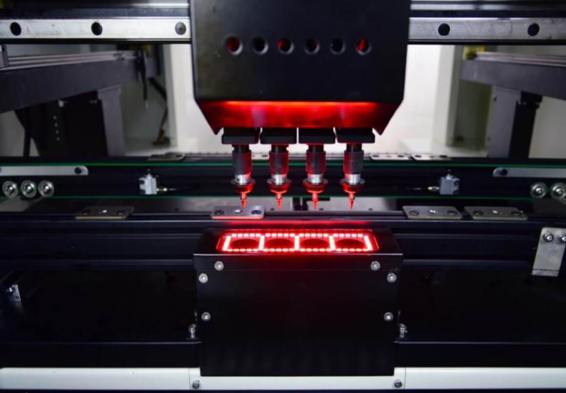
4 groups of component recognition camera
The latest desktop pick and place machine is provided by ElectronicsTalk, it is equipped with 4 units of component recognition cameras to make alignment during the process.
The special design reduces the time of component recognition, which improves production efficiency.
- Verifies that the part is picked up and is on the nozzle. it’s easy for the machine to not devour the part and keep going without learning a neighborhood.
- Aligns the board. once you start employment and put the board within the machine vision, it’ll search for marks on the board called fiducial markers. This becomes even more important because the parts become smaller.
- Helps align the pickup points and identify where the feeders are. albeit you’ve got the mechanical position of the parts correct, you’ll be off by a millimeter. the matter occurs when the part is simply half a millimeter.
4.3 Speed of Placement
This is important because it decides the productivity that you simply could get out of your machine.
More importantly, the desktop pick and place machine provided by ElectronicsTalk can reach a maximum actual placement speed of 13,000 CPH, which is one of the best models in the same class in the world.
When the desktop pick and place machine mounts both RC and chip components together, the 4 spindles will be combined to work and reach an actual speed of 5,000 CPH.
For a desktop pick and place machine, the above placement speed is totally enough for normal SMD production. Besides, it comes with a very low price, which is very cost-effective.
Usually, low-end machines aren’t getting to do quite 10 or 20 pieces per minute. this could not be a drag unless you’ve got tons of placements.
For systems with machine vision, switching it off should offer you a significant increase in the speed of placement since it now doesn’t need to verify the location of each component.
Other features that will be considered include the littlest size of the part which will be picked. Currently, one among the littlest is 0402 imperial, which translates to 1mm×0.5mm.
Solving the PCBA industry biggest problems
Working with ElectronicsTalk offers you high-standard PCBA products that are supplied from credible manufacturers in attractive cost.
We dedicate to provide the best customer support, its the vital aspect of our company philosophy.

