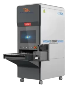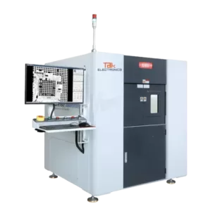
ET X5 PCB Xray Inspection Machine
ElectronicsTalk is referred to as an organization that provides the latest technology in PCB inspection machines, and they have introduced their newest version called ET X5 PCB Xray Inspection Machine. It adopts the Japan Hamamatsu X-ray source and Korea Rayence flat panel detector, which ensures high-accuracy of focal spot size and pixel size. As a result, a clear X-ray image is capable to be produced.
Besides, it has a large detection area of 530×530 millimeters, which meets the inspection requirement of big PCB boards.
What’s more, its software system is also highly intelligent and automatic. There are image effect adjustment method, display real-time coordination, movement speed control, void rate automatic calculation, etc.
Types of X-Ray Solutions

Microfocus X-Ray Inspection System ET X5
Features of Microfocus X-Ray Inspection System
Hardware Parameters of PCB x-ray inspection Machine
Hardware Parameters of PCB x-ray inspection Machine
| X-ray source | Brand | American Thermofisher |
| Type | Closed, microfocus | |
| Max tube voltage | 130kv | |
| Max tube current | 200μA | |
| Focal spot size | 2μm | |
| Flat panel detector | Function | Auto preheat |
| Brand | China Yirui | |
| Effective area | 58mm*54mm | |
| Pixel size | 85μm | |
| Resolution | 1536*1536 | |
| Frame rate | 30fps | |
| Table | Tiltable angle | 70° |
| R axis | 360° | |
| Detectable area
Max load |
500mm*500mm
10kg |
|
| Equipment | Magnification | Geometry 300X System 1000X |
| Inspection speed | Max 3.0s/point | |
| Dimensions | 1385mm (L) * 1250mm (W) * 1745mm (H) | |
| Weight | 1500 kgs | |
| Power supply | AC110-220V 50/60HZ | |
| Max power | 1500W | |
| Industrial PC | I7 CPU, 16G RAM, 1TB Harddisk WIN10 | |
| Displayer | 27 HDMI LCD | |
| Safety | Radiation leakage | No leakage, international standard: ≤1μSv/h |
| Lead glass observation window |
Transparent lead glass window shields radiation to observe the inner status. | |
| Window and back
door safety interlock |
Once users open the window or back door, X-ray tube will power off immediately. When the window or back door is open, users can’t turn on the X-ray. | |
| Electromagnetic Lock | once the X-ray is on, users can’t open the | |
| safety switch | observation window. | |
| Emergency stop | Next to the operation position, press to power off | |
| Tube protection | User can’t leave the software to if you don’t close the X-ray tube. |
Dimension of PCB X ray Inspection Machine
| Function module |
Operation | Keyboard and mouse can finish all operations |
| X-ray tube control | Using mouse to click the X button can turn on or off the X-ray. The real-time tube voltage and current value will display beside, users can click up and down button, or drag the slider, or type to adjust. |
|
| Status bar | Indicates the interlock status, pre-heat status, and X-ray status by flashing alternately red and green. |
|
| Image effect adjustment |
The brightness, contrast and gain of the image can be adjusted freely to achieve a satisfactory result. |
|
| Product list | Users can save the inspection parameters such as Z-axis position, brightness, contrast and gain, and can directly call the parameters when inspecting the same product, to improve the inspection efficiency. |
|
| Navigation window |
After the camera takes a photo of the table, click anywhere in the photo, the table will move to the place you click and display on the screen. |
|
| Motion axis status | Display real-time coordinates. | |
| Inspection result | The measurement results (voids rate, distance, area, etc., set by users) display in order. |
|
| Speed control | The movement speed of each axis can be adjusted to slow, normal and fast. |
|
| Voids rateAutomatic calculation |
Automatic calculation |
Click on two points to determine a rectangle. The software automatically finds and measures the edge of the solder ball in the rectangle, the pad and the internal voids, and can get the data of the voids rate, he area of the solder ball, the circumference, the biggest void’s rate, the length and the width, and indicates NG or OK by red and green. |
| Parameters adjustment |
Users can adjust the grayscale threshold, pixel, contrast, size filtering and other parameters to get accurate results of automatic calculation. | |
| Add voids manually |
Users can draw a polygon or a free figure and calculate it as a void into the void rate. |
|
| Save parameters |
Users can save parameters such as grayscale threshold, pixel, contrast, size filtering and other parameters, and can directly call the parameters when detecting the same product, to improve the detection efficiency. |
|
| Distance | Click the A and B points to set as the baseline, then click the C point to measure the vertical distance from the C point to the baseline. |
|
| Other measurement function |
Distance rate | It is mostly used to measure the soldering rate of the through-hole. Set one more point “D” than the distance. Divide the vertical distance from the D point to baseline by the vertical distance of the C point, to obtain the percentage ratio of the vertical distance of D to C. |
| Angle | Click the A and B points to set as the baseline, then click the C point to measure the angle between the BA and BC rays. |
|
| Radius | It is mostly used to measure round components such as solder balls. Click three points to determine a circle and measure the circumference, area and radius. |
|
| Perimeter | It is mostly used to measure square components, click two points to determine a square, measure the length, width and area. Users can set any positions on the table as inspection |
|
| Image Detection Software |
Manual setting | points, the software will automatically inspect and save the picture. |
| Skills to Analyze |
Analyze and judgement of BGA short circuit, open circuit, void, general soldering defects, etc. Even QFN, Transistor and IC Packages. |
|
| Software Processing Capability |
Image inversion, sharpening, histogram, binariation, 3 3D Stimulation for better analysis and X-RAY Image |
Working Principle of PCB X-ray Inspection Machine

Application Example of PCB X-ray
Application Example of PCB X-ray

BGA solder bridge

BGA solder voids
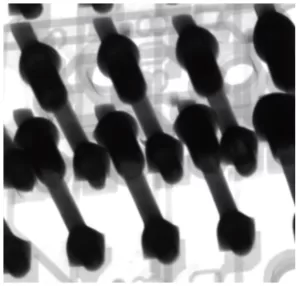
PCB through-hole
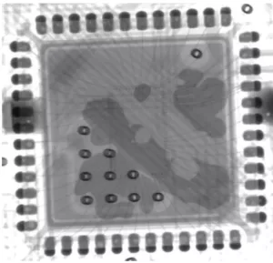
IC voids and gold wire
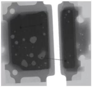
BGA solder bridge
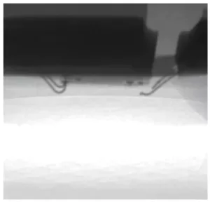
LED gold wire crack
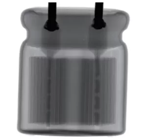
Capacitor

Inductor

Sensor
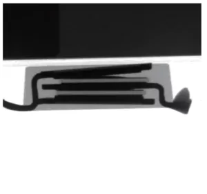
Thyristor surge suppressors
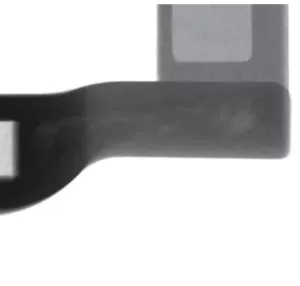
Fiberglass
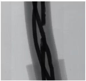
Cable
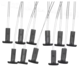
Diode

Steel pipe welding gap
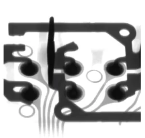
Automobile electronics
Sealed Hamamatsu X-Ray Source 90KV
Overview of Hamamatsu X-Ray
The Hamamatsu Microfocus X-ray sources were developed particularly for
X-ray non-destructive inspection system. These X-ray sources use an X-ray
tube with a small focal spot of several micro-meters to 10 micro-meters,
capable of producing a clear X-ray image even at a high magnification. The
RS-232C interface is provided as a standard feature,allowing automatic
operation by external control.
The X-ray tube has an air-cooled and hermetically sealed structure, and
is integrated with its high voltage power supply for easy handling.
(High voltage cables are not required.)
Application
BGA , CSP , Flip Chip, LED , Fuse, Diode, Sensors, PCB Voids
Semiconductor , Battery Industry , Small Metal Casting, Electronics
Cables and Connectors, 3D Printing Module, Medical Device and Parts.
Key features
Hamamatsu X-Ray Source Features:
- Focal Spot Size: 5 μm, enables sharp and clear X-ray images even at a high magnification
- Easy Handling: fully operable from an external PC
One package of a sealed type X-ray tube, a high-voltage power supply and - a control function
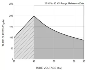
Voltage and Current Range
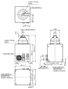
Dimention Outline
Specification of Hamamatsu X-Ray
| GENERAL | ||
| Parameter | Description / Value | Unit |
| Input Voltage (DC) | 24 | V |
| Power Consumption (Max.) | 96 | W |
| Operating Ambient Temperature | +10 to +40 | C |
| Storage Temperature | 0 to +50 | C |
| Operating and Storage Humidity | Below 85 (No Condensation) | % |
| Weight | Approx. 9 | kg |
| Conformance Standards | CE (EMC: IEC 61326-1, Group1, Class A) | – |
| Operation | Continuous | – |
| High Voltage Power Supply | Built-in | – |
| X-RAY TUBE | ||
| Parameter | Description / Value | Unit |
| X-ray Tube | Sealed Type | – |
| X-ray Tube Cooling Method | Convection Cooling | – |
| X-ray Tube Window Material / Thickness | Beryllium / 150 | μm |
| Target Material | Tungsten | – |
| Tube Voltage Operational Range | 40 to 90 | kV |
| Tube Current Operational Range 1 | 10 to 200 (8 W Max.) | μA |
| Maximum Output | 8 | W |
| X-ray Focal Spot Size | 7 (5 μm at 4 W) | μm |
| X-ray Beam Angle (Coned) | 30 | degrees |
| Focus to Object Distance (FOD) | 11 | mm |
| X-RAY CONTROL PART | ||
| Parameter | Description | Unit |
| Function | Tube Voltage and Tube Current Preset / Auto Warm-up | – |
| Protection | Interlock | – |
| External Control | RS-232C | – |
| Applicable OS | Windows® 2000 Professional, XP Professional | – |
| Computer Operating Conditions | CPU: Intel Pentium or Higher, Memory: 64 MB or More | – |
The Benefits of Using X-Ray PCB Inspection Machines
Here is a summary of some of the key benefits of using X-ray PCB inspection machines:
- High-resolution imaging allows the detection of microscopic defects – X-rays can penetrate boards and components, revealing issues like cracks, voids, missing connections, or foreign objects that visual inspection would miss. Resolution down to a few microns is possible.
- Rapid whole-board inspection – X-ray imaging allows the entire board to be scanned at once, rather than inspecting individual sections visually. This allows for faster throughput and detection of defects across the entire board.
- Repeatability and objectivity – Machine inspection is consistent and objective, while manual visual inspection can vary between operators. This improves quality control.
- 3D inspection capability – Some X-ray systems generate 3D models of boards and components, allowing more thorough inspection from all angles.
- Wide range of board sizes – Small boards and large panels can be accommodated by adjusting the X-ray camera setup. No size limitations like with optical inspection.
- Material agnostic – X-rays penetrate metals, plastics, ceramics, etc allowing inspection of complex multi-material boards. Component type and board thickness have minimal impact.
- Detects issues like solder defects, contaminants, and placement accuracy – Besides physical defects, X-rays can identify botched solder joints, unwanted foreign objects, misalignments, and more.
The combination of high resolution, rapid throughput, and ability to detect minute defects makes X-ray invaluable for quality control in electronics manufacturing. Implementing X-ray inspection improves product quality and reliability.
The different factors to consider when choosing an X-ray PCB inspection machine
Here are some key factors to consider when selecting an X-ray PCB inspection machine:
- Image resolution – Higher resolution allows seeing smaller defects. Typically measured in microns. Sub-micron resolution is best.
- X-ray source power – Higher power allows the penetrating of thicker and denser boards. 30-160kV sources are common.
- Detector technology – Newer CMOS detectors offer faster scanning and lower noise than CCDs. Resolution and pixel size are also factors.
- Size and thickness capacity – Machines differ in the maximum PCB size and thickness they can handle. Pick one that matches your products.
- Conveyor speed – Faster conveyors mean higher throughput. Important for high volume production. Speeds from 10-200mm/second are typical.
- Software capabilities – Software for analyzing images, defect detection, generating reports, etc. Should have sufficient analysis tools.
- 3D inspection – Some systems offer 3D scanning capability for thorough inspection. Useful for complex boards.
- Price – Initial cost plus ongoing maintenance and consumable costs. Balance capabilities with budget.
- Footprint – Larger systems take up more factory floor space. Consider available space.
- Ease of use – Software and controls should be intuitive for operators. Extensive training adds costs.
- Company reputation and support – Established vendors offer better support and are less risky.
Considering these factors will help identify the right X-ray system that meets inspection requirements within budget constraints.
The latest trends in X-ray PCB inspection machines
Here are some of the latest trends emerging in X-ray PCB inspection machine technology:
- Higher resolutions – Newer microfocus X-ray sources allow sub-micron resolution imaging to detect even microscopic defects.
- Faster line scan rates – High speed line scan cameras reach speeds of over 200mm/second conveyor movement allowing rapid inspection.
- Integrated 3D inspection – 3D X-ray imaging is being integrated into inspection processes for complete board visualization.
- AI-enabled defect recognition – Machine learning is being applied to automate analysis and identify defects without operator input.
- Large panel inspection – Larger conveyors and scanning areas are being developed to handle PCB panels over 2×2 feet.
- Dual angle inspection – Adding ability to scan boards from multiple angles gives more complete inspection.
- Inline integration – X-ray systems are being integrated into manufacturing lines for live in-process quality control.
- Cloud-based imaging – Scanned images are being uploaded to the cloud for remote analysis and data analytics.
- Virtual reality visualization – Scanned 3D board data can be viewed and manipulated in VR for immersive inspection.
- Automated reporting tools – Systems generate inspection reports, trends and analysis without extensive manual work.
These trends aim to make X-ray inspection higher resolution, faster, more automated and a seamless part of the manufacturing process. This allows maximizing quality and minimizing defects.
Solving the PCBA industry biggest problems
Working with ElectronicsTalk offers you high-standard PCBA products that are supplied from credible manufacturers in attractive cost.
We dedicate to provide the best customer support, its the vital aspect of our company philosophy.


